Update 20 Nov 2017
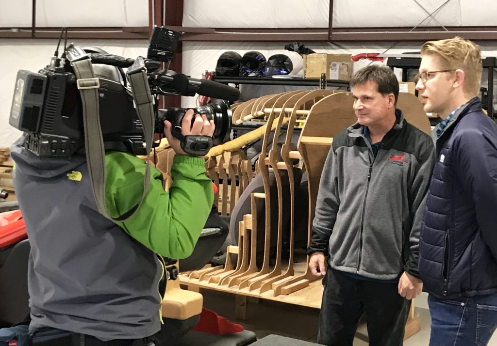
Samson was in the news recently, this time with a Portland, Oregon, CBS affiliate, KOIN TV. Pictured in the image above, Reporter Cole Miller and Videographer Mike Soe drove three hours from Portland to do an in-depth TV News segment on the Switchblade, which aired late last week. This story was picked up by other regional CBS affiliates, with stories airing in Los Angeles and other metropolitan areas around the US. The KOIN team were fun to work with, and excited about our project. We look forward to working with them again.
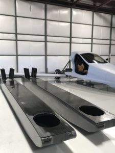
We recently received our second tail boom from the experts at Phoenix Composite Solutions in Michigan. The two tail booms are shown below, side by side. They are identical, and one will be tested to certified aircraft standards, and then tested further until something in the boom fails (breaks). We wanted to test the boom beyond certified standards so that we know when, how, and where it will break when pushed beyond its limits. If there are no changes needed, we will use the second tail boom in the Pre-Production Prototype for flight testing.
The Switchblade tail boom is over 6 feet long and it slides into the opening at the top of the cabin fire wall – the wall at the back of the cabin. The booms are shown here, with the top side resting on the table, bottom side up. The little vertical pieces sticking up from the boom at the far left of this photo are for attaching small, fixed vertical stabilizers – which help keep the vehicle flying straight.
In a complicated curvy shape like the back end of the Switchblade, this takes some thought and planning to ensure that the joggles will allow an easy build of the overall part. In the image below, the red portion is the bumper section, which has to be able to move relative to the rest of the body (in an accident). We want it to move in ways that are the least damaging to the more expensive parts forward of the bumper!
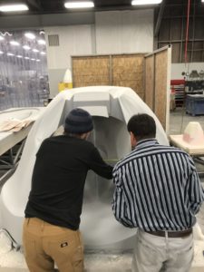
While the computer is useful, everything gets side-checked in real life. Below, Todd Guess is showing Sam the critical dimensions of the plug that the molds will be developed from. The molds are negative shapes that you lay carbon cloth in and let it harden into a positive part, that is then removed from the mold. One way to get that negative shape, is to lay composite material over a positive shape and then pull it off after it hardens. That is the process we are engaged in at this time: to go from positive to negative, and then back to positive with the part.
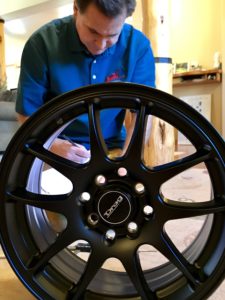
The wheels we have chosen are nice, light weight aluminum wheels from Drag Wheels in Sacramento, California. Working with Drag Wheels has been very easy and fun, and we are expanding the range of wheel choices available to Switchblade owners. Each item in a flying vehicle is weight critical, so you can’t just bolt on any wheel choice. Items need to remain within a weight range so that you know that you are not making the Switchblade too heavy to fly safely when you change such things as wheels and tires. We have been doing the work for you, so that when time comes to outfit your vehicle with tires and wheels, you will know what your options are. Below is the latest wheel that we have accepted as an option.
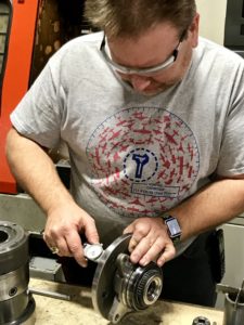
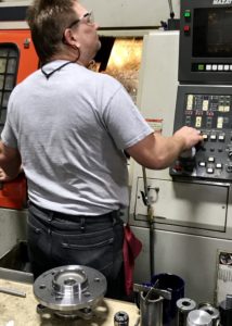
To accelerate the Switchblade to take-off speed more rapidly, we are allowing the rear wheels to be powered by the engine – along with the propeller – until take-off speed has been achieved. Below, Kevin Risse of Risse Racing in Redmond, Oregon, is shown modifying a Ford 4WD wheel hub to work with our wheels, brakes, and tires. He is re-locating the wheel lugs (bolts that hold the wheel to the hub) to match the wheels so front and rear wheels can be the same. At Samson’s direction, he is removing excess material from the Ford hub. The Ford hub was designed for very heavy trucks, but has a nice disconnect mechanism that we would like to incorporate. Since our rear suspension will be tested to certified aircraft standards, like our front suspension already has been, we are not concerned with the removal of material at this point. We need to reduce the weight of the wheel hub to reasonable levels, and then we will test the assembly. If it passes, we know it is strong enough the way we have modified it, and can continue to use that design for our production vehicles. So far we have lost six pounds from each wheel hub.

