Engineering shifted into high gear since the last post, as we are pushing hard to get the tail caught up with the body progress. We want to have two build teams working – one on the body and one on the tail. Concentrating on the engineering means we have less building progress to show, but much work is being done! Below you can see the interior workings of the tail where it locks into place after extension. This is a work in progress, but basically, we are locating and choosing all of the interior pieces that make up a working tail. Some of this is custom-built, and some is off-the-shelf components.
At the same time, the rudder Fly-By-Wire system is being wrapped up. As you may remember, we went to a FBW rudder as the safest way to handle the rudder control in the tail of the Switchblade. Rudders act to shift the nose left or right to compensate for wind direction, mostly on landings and turns. Based on the system requirements we found during our initial testing, we researched electric actuators. We located ones that were lighter than our initial actuators by two pounds each, and had a more durable gearing system. These new actuators also have a built-in alignment system that will spot where the rudders are at all times so that the twin rudders are almost impossible to become or remain out of alignment. Remember we have two rudders, with one actuator for each rudder.
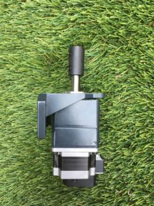
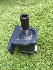
The two images below show the new electric actuator, which is a specifically designed electric motor with a gearing system to amplify the power of the motor. There is a coupler at the top which connects the actuator to the bottom of each rudder directly, eliminating any mechanical linkage commonly found in typical pushrod systems.
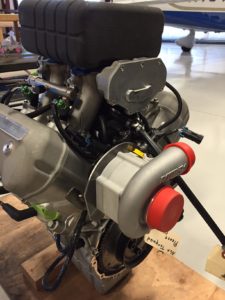
We also mounted the supercharger onto the V-4 engine, and are working on the belt drive system, including a tensioner for the belt. This is just a temporary mounting so that we can get the engine to the dyno shop and have the twin computers installed and operating. A dynomometer is used to measure the power of the engine being tested so that you can tweak the engine computers for best performance in fuel economy and power. The image below shows the supercharger mounted on the rear of the motor with the red caps still on the inlet and output of the supercharger. This particular supercharger is from Rotrex, and has a unique method of gearing inside. Any supercharger needs to run faster than the engine, so there are gears built in to spin the supercharger fast enough to do its duty. In this case, instead of gears, there are cylinders that are the shape of gears, but do not touch each other. Rotrex used a specially designed oil that, when compressed, becomes semi-solid. As the cylinders rotate next to each other, the oil is squeezed between the rollers and locks up in a way that transfers force from one cylinder/roller to another without metal touching metal. The result is a supercharger that lasts for a very long time.


