

We have been so busy getting ready for AirVenture that we haven’t taken time to post our progress! Not good! Hope you forgive us. Below, Sam Bousfield is shown helping to ‘carve the turkey’, which is one way to describe the process of sorting out how produce the least molds for the best building of the rear of the vehicle. This area is large, and has tight tolerances near the propeller to maintain the efficiency of the ducted fan propeller. There is also a bumper area that has to be replaceable in case of accident. With all of this to deal with, the large solid plug is being used to verify where to put mold boundaries so that we can produce the best build of this area.
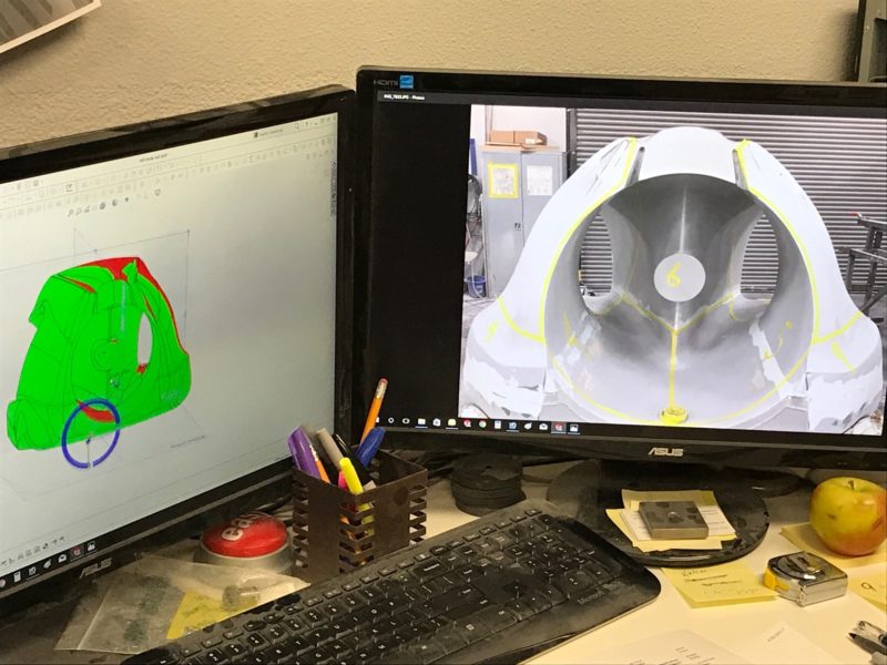
Another tool that is used is to put the 3D model into the computer program that allows us to review different scenarios of parts. The green parts in the image below (left) show how Todd at Composite Universal Group in Warren, Oregon, can manipulate the model to choose areas that can be removed from the mold once made. If it is red, it would be trapped by the mold from the direction chosen. If green, it would come out of the mold. As in many areas of life, green is good! An image of the rear of the Switchblade is used for reference (right).
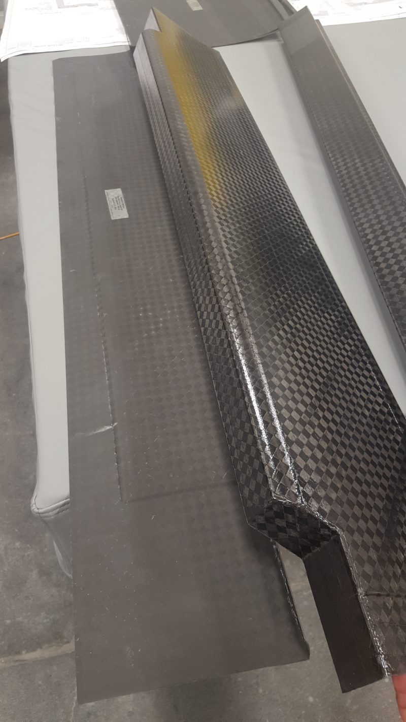
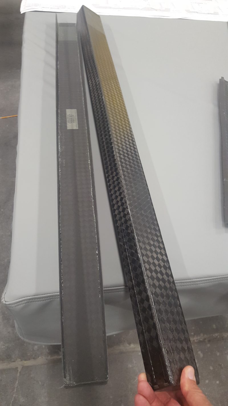
While the molds for the rear end are being designed, the molds for the tail are mostly made, along with parts for the tail. We are almost half-way through all of the tail molds, and one third through making the parts for the tail at this point. Below you can see the elevator skins and other parts for the tail.
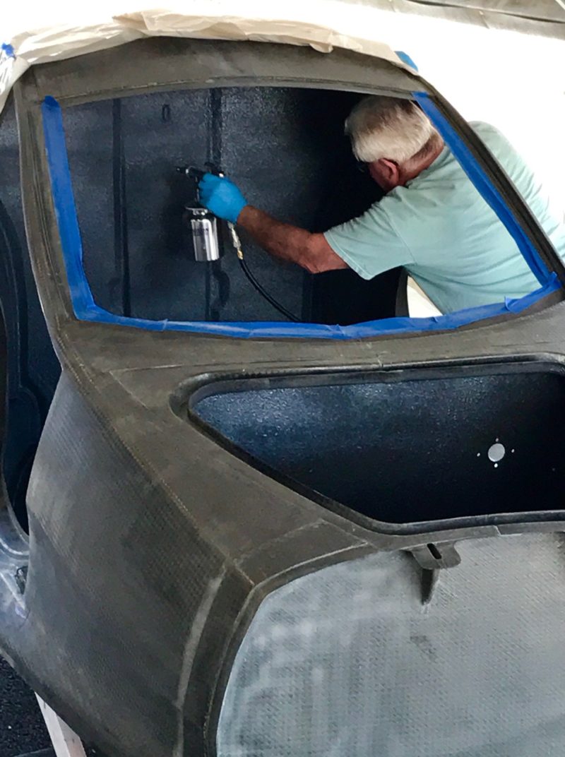
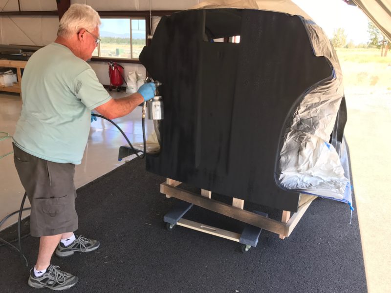
For the Switchblade cabin, research was done to sort out the most effective sound dampening. We chose Lizard Skin for acoustic coating of the cabin to dampen both the engine nose from the rear, and the wind noise as you fly along at 160+ mph. Below Ron Burch is shown spraying the Lizard Skin acoustic coating on the inside of the cabin body, and below that he is spraying the Lizard Skin thermal coating on the rear of the cabin where the engine bay starts.
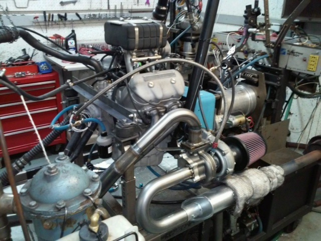
Speaking of the engine, Loyning’s Engine Services of Portland, Oregon, finished the install of the turbo-charger and the intercooler, and Arnie Loyning and John Reed teamed up again to tune the engine with the new setup on the dynomometer (dyno for short). Engine dyno tuning is used to verify that you have the correct engine programming, and although this engine has been tested extensively in non-turbo conditions, we felt it would be best to re-tune the engine computers for the added horsepower at lower rpm that the turbo provides.
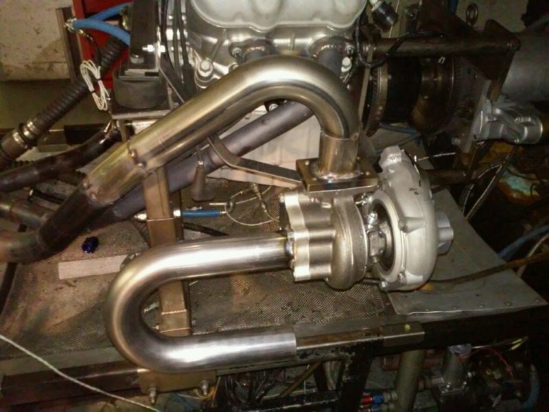
We were successful in achieving 211 horsepower at 5,600 rpm, which is significantly better than the previous 200 hp at 6,100 rpm. The lower the rpm, the better it is for engine longevity. We now have more horsepower than we can use, so will tune one more time to increase fuel economy and driving performance. Below is the turbo setup, which should also quiet the engine a bit more without adding more mufflers. There will be added heat in the engine compartment, so we are directing air flow at the turbo to cool that area during use.
Composite Approach, in Redmond, Oregon, has been busy as well. They just put the nose cone in the oven after bagging the carbon fiber part (see below). The nose cone is to be replaceable, like the bumper section, so that in case of an accident, it can be repaired, or replaced if needed. Big part! Can’t wait to see how it looks, and then begin mounting it and installing the headlights.
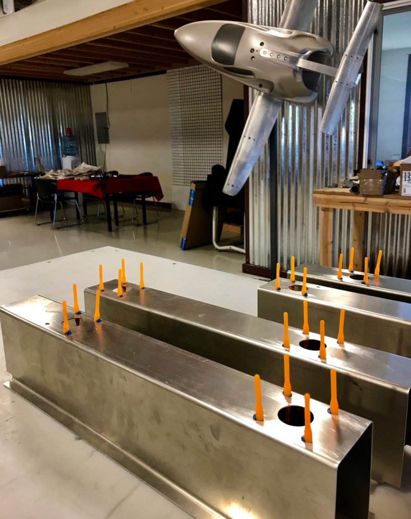
At the hangar, Ron Burch bonded the Clickbond nut plates, which act as fixed nuts in tight places and allow bolting and un-bolting where you can’t reach the nut. The forest of orange plastic stems are the plastic pulls that fill the nut plate bolt hole and allow you to pull them tight for bonding, but keep the glue out of the holes. Once these dry, the orange pulls will be removed and the seats bolted up to these aluminum seat beams. The seat beams provide support for the seat, but the seat beams are designed to crush on hard landing to protect the occupants from harm.
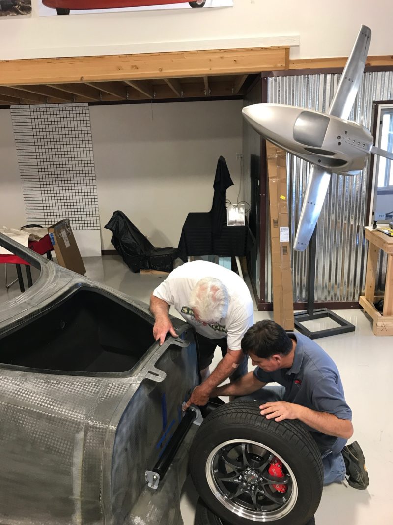
Some really big news is that our front suspension passed the FAA requirements for Certified Aircraft. Although we are an Experimental Aircraft, we design to Part 23 Certified Standards, and were very pleased that the front suspension passed the harsh testing mandated by the FAA for Certified Aircraft. And we accomplished this on our first try. That doesn’t always happen, and there is often some re-design of the landing gear to handle deficiencies. Kudos to the engineering team and fabricators at CLS in Bend, Oregon, for doing a good job! Now the front suspension is being bolted up to the prototype, as shown below.
Also happening at Composite Approach is the building of the doors. This involves making door skins, and an interior door reinforcing panel. The reinforcing panel is similar to a car, as it has to allow access to the door interior for repair of the electric window mechanism and openers, but be strong enough to handle the door hinge and latch requirements.
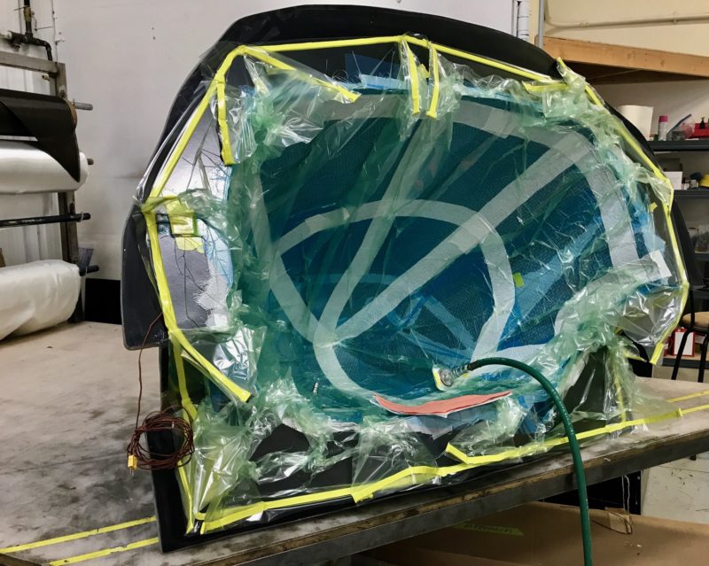
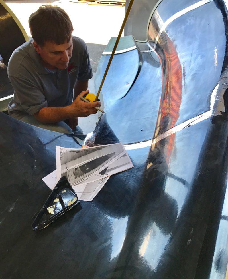
Providing a proper space for the window is also critical, and Sam is shown below taping out the window and window molding locations prior to this part being made. There is a lot going on in these doors! You have windows, latches, switches, mirrors, and much more – all in a tight space.
We have way too much to show here, so will do a better job of providing weekly updates with shorter posts. Thanks for checking in!