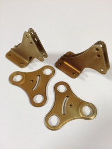
We had the aluminum pieces made that act within the wing to transmit the pilot’s input into the aileron movement, which banks the aircraft left and right. This is called a bell crank (don’t ask me why!). Above are the pieces before treating with an anodizing finish, and below you see them after the treatment. The anodizing puts a hard coating on the aluminum so that the metal lasts longer and retains its finish for many decades.
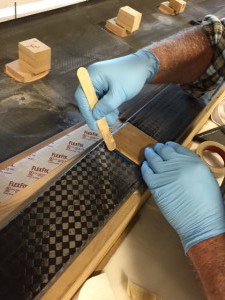
Next we created two aluminum backing plates to reinforce the mounting of the aileron bell crank. Each wing receives one bell crank and one mounting plate, so below is the first backing plate being bonded to the left wing spar. It is bonded in with the two part adhesive, Hysol, which in this mixture is blue colored. The spar, as you remember or know, is the main structural ‘beam’ of the wing.
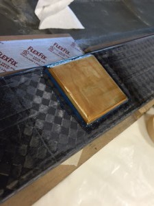
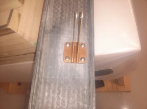
Above is the finished mounting of the reinforcing plate, which was then drilled for the aileron bracket bolts. Below the aileron bracket is shown mounted to the side of the spar, on the opposite side from the reinforcing plate.
There is an access hole in the lower skin for maintenance of the bell crank pictured above. We also created a mold for the access plate and hole in the underside of the wing, made the access plate, and next will add the nut plates to the lower wing skin inside the wing to receive the bolts holding on the access plate. The nut plates are from ClickBond, which are really useful fasteners commonly used in aircraft construction. They are bonded inside structures and become a part of the carbon part, so they can’t come loose and rattle around inside the wing like a typical nut could.
When the access hole is finished, we will bond the spar to the bottom skin, and then the ribs. After that, the aileron actuating tubes and hardware get connected, along with the hinges below the wings for the ailerons and flaps. More to come!


