

Apologies for not posting more update news. We have been busy! Here is what I can tell you. All of the molds for the body are completed, and the engineering re-evaluation of the structures for the body are finished. What we found was that there were a few areas that needed additional reinforcing in the existing body panels that had been made, and some changes to be made to the next body pieces (in the pipeline now). Luckily for us, many of the body panels are simple molds called picture frame molds, which are when you have a (mostly) flat piece like a bulkhead, and just need the outline of it including the outside flange (portion that parallels the skins for bonding). These look like this:
The above image is of the intermediate bulkhead which forms the forward portion of the cockpit where your feet go. The most forward bulkhead is where the front suspension is mounted just behind the front wheel. You may have seen this one already, but here it is again: 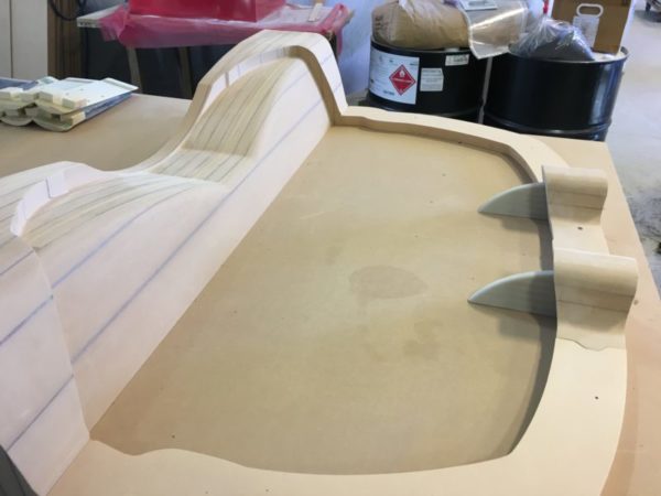
Molds are pretty wild, as they are the negative of the part. You have to imagine what a part made from a mold might look like. For instance, the mold pictured above would make a part that looks like:
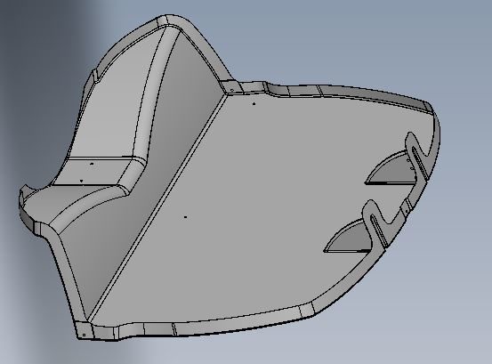
The top is to the right and bottom of the part is to the left. This is a vertical bulkhead with slots for hinges at the top, and a depression in the bottom to give room for the front tire as it swivels left and right. There will be a small compartment in the front ‘hood’ area that will house some electronics, the windshield wiper motor, washer fluid, intakes for fresh air, and the hinges are for the top hood panel.
The electric fly-by-wire rudder was taken to the next step, and we found that the operation was quite smoothed out, and working with good speed. We don’t feel there will be any chance that the aerodynamic forces acting on the rudder will at any time overpower the electric motor that would power each rudder. These little motors turned out much stronger than anticipated, while being less weight than the previous one. We will keep the extra power as safety margin, as it isn’t costing us any weight penalty. The motors also have a self-centering feature, so they always know where they should be, if they were somehow pushed out of position.
The graphic artist finished the ‘eyes-forward’ display, and it was sent to the electronics engineer to translate from a graphic to a digital display. As you recall, this display will shift from Ground Mode gauges for driving, to Flight Mode Gauges for flying. There are a few more tweaks to the display, and to show it doesn’t do justice, as there are items which rotate through (changeable display so you can see multiple gauges in one spot). The default display will look something like:
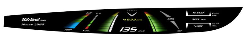
This is the flight display, and the Fuel Gauge is too thin, and is being widened. A few more tweaks and it may even be ready for prime time! We will also have alternate displays, so that a person can change from this (a more modern display) to a round gauge display if they are more comfortable with that. We found by survey that this is one area with very little common ground, so having changeable configurations may be the way to go. This shows digital readouts and colored bars. The bar will glow to show where you ‘are’ on the scale. The digits will indicate the number value. This way you get a relative, and an actual, representation of conditions of flight. To the right you have height above sea level (what altitude you are flying), which is the main data required for maintaining correct flight level. You also have height above ground so you can tell how far above ridges or mountains you might be flying. In between those two you have the compass direction you are flying.
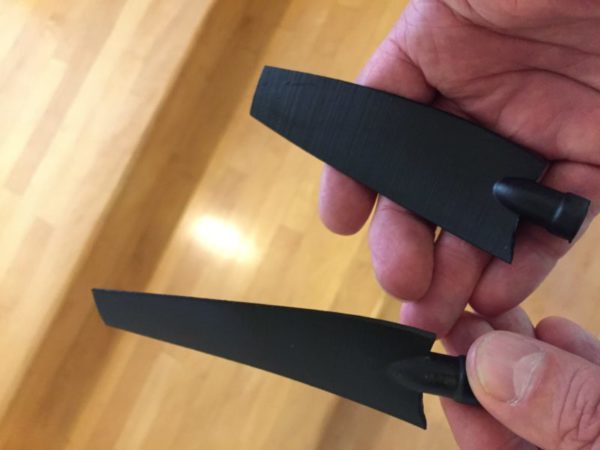
We are beginning to use 3D printing more, and wanted to try out some material and print speeds on a small part, so chose to print the propeller in quarter scale to be mounted on the existing wind tunnel model, now used as a display. This is how it turned out – pretty nice! The real propellers are being made out of carbon fiber, along with the five blade hub out of machined aluminum. We hope to see the final pieces this month.
There is a lot that has happened in the last month, so I am going to break this into two posts. I will do another one in a week or less, and you can see the rest of the progress. I don’t think I have shown you even half of what was accomplished.
Thanks,
Sam