Risse Racing provided the two newly re-worked rear shock absorbers last week. These are two-stage shocks, which were developed to take into account the difference between aircraft shock requirement (worst case – handling the forces when you come in hard when landing), and driving requirements (providing comfortable ride and controllable vehicle in turns). These shocks have compressed nitrogen as the spring portion. Normally, shocks have a metal spring, but for aircraft, weight is king, so we opted for a nitrogen spring. Having higher pressure in the main nitrogen chamber works for the aircraft portion, and having less pressure nitrogen in the oil chamber for the second (lower) spring, provides for driving comfort. We have passed the requirements for an FAA certified aircraft test of the front suspension, so will now make the rear suspension and do the testing on that before mounting the shocks in the flying prototype. The image above shows the new shocks, sporting the Samson logo.
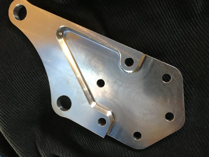
Shown below is the first of the many metal parts of the tail which are starting to arrive. There are nearly 30 different metal parts that make up the tail, along with the numerous carbon parts. These parts provided by eCNC in McMinnville, Oregon, were nicely finished. This is a hinge bracket that connects the horizontal stabilizers to the center tail section. The horizontal outboard parts fold for ground use. This is one of four hinge parts to support that movement and allow a metal pin to fix the horizontals into position when extended for flight. You will see more parts in the near future as we get ready for the tail assembly.
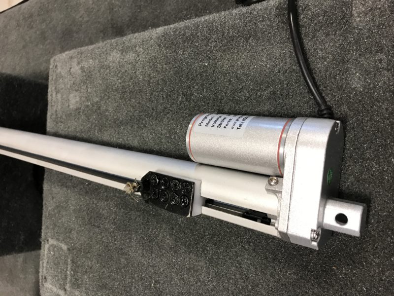
The wing swing is powered by an actuator that we tested while at AirVenture this year, shown in the image below. The wings were swung in and out almost continuously during the week-long event. We put a conservative estimate of 3.5 years of use on the actuator before any maintenance was required. A little additional grease, and it was ready for action again. We feel we have proven this actuator, and are having a custom length made for our use that allows full retraction and extension at the push of a button. James Bond will have nothing on us! Well, almost nothing. Okay, he has quite a bit on us, but he doesn’t have a flying sports car (yet)!
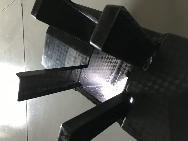
I don’t know if you saw our earlier images of the tail boom made by Phoenix Composite Solutions, but it is really a nice piece of carbon. The image below shows a shot of the rear end of the boom, where the lower fixed vertical stabilizers will be attached. The lighting was to highlight the unique nature of this piece, and the boom is almost ready for assembly. The boom is shown on its back, with the stubs sticking outwards ready for us to attach to the fixed vertical wings. The light is coming from the access hatch area, where we can provide maintenance access to the rear of the boom.
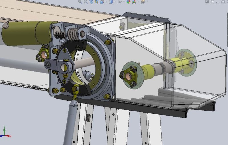
The rear of the boom has a lot going on it in, as the tail rotates at this point, and there is a rotating mechanism, and a locking mechanism that keeps the tail in position during flight. The engineering drawing below shows this area with the tail boom in the upright position, with the boom skin left transparent to allow viewing inside. The locking mechanism is shown to the right, and the rotating mechanism to the left. The stubs talked about above are shown at the bottom of the boom below. Simpler would be better, but this will surely do the job!


