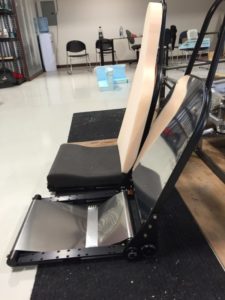
Body parts are being made, and will soon be assembled, but in the meantime we needed to dive into the dashboard, brakes, gas pedal, rudder pedals, etc. To really make sense of all of that, and validate the 3D engineering that was done, we decided to start with the seats. The seat frames were chosen after a lengthy review (this choice was particularly important due to all of the functions and demands of a seat). In our case we ended up with seat frames from another aircraft manufacturer – Lancair. These have been tested to withstand a 19G impact in a vehicle, so we have confidence that they will be adequate to the task.
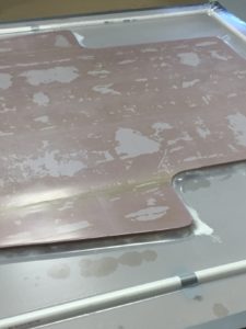
The frames were also fairly light weight, which will help with the overall vehicle weight. The image above is of one these frames, which are adjustable for leg and back position (tilt). We may add an adjustable lombar in the future, but for the test aircraft, it will have a fixed lombar support.
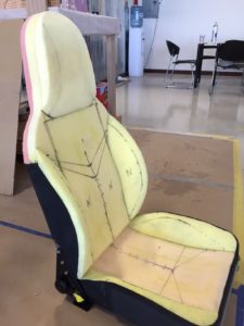
Below you see the customized seat ready for upholstery. There are stitch lines on the foam, which will show up in the finished seat. Leather choices were made to match the paint scheme of the dash display, and the leather is now being shipped. We had to use leather that has been treated for UV protection, fire retard capability, and for scuff resistance. This is a premium grade leather, but we feel worth the extra effort and cost.
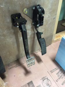
With the seats chosen and in final form, we were able to take measurements so that we could place the gas and brake pedals where they would be, as well as confirm steering wheel location, and dash size and shape. The pedals are shown mounted in the image below. This mock-up is for validating only, as we don’t have this type of construction in our final vehicle. This structure is of fiberglass, and our final vehicle is made from carbon fiber. VERY different in look, feel, and weight (much lighter).
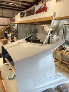
The dashboard display mock-up is being made to take to AirVenture in Oshkosh, Wisconsin, later in July. We are using this mock-up as a way to verify pedal, seat and dash placement and sizes prior to making the expensive tooling for production, and to look at preliminary designs to make sure that they function the way they should. The display mock-up is a partial body segment from just in front of the passenger compartment to about the first quarter of the door. There will be seats mounted in the correct position, and you will be able to sit in the cockpit at AirVenture if you are there. The image below shows the shape of the body in the vicinity of the dashboard.
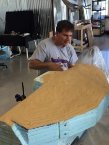
The dash section and seats will be mounted on a base that is the same height off the floor as the Switchblade will be. The base was created by sandwiching two inch foam between layers of fiberglass reinforcement. As is often the case with composite construction, the fiberglass is applied and then saturated with resin, and then a plastic cover is pulled over the top and taped down so that vacuum can be applied to remove air and excess resin. This process is shown in the image below, and you can see the plastic being pulled over the foam and fiberglass by suction.
The dashboard itself was earlier carved out of foam as a base, and is now being covered in automotive design clay. That is how we are getting the final shape worked out, and then that shape will be used to make a mold for a fiberglass dashboard for the mock-up. You can see the action in the image below.

